| Version 5 (modified by , 13 years ago) ( diff ) |
|---|
How to calculate "real" parameters from affine transformation
Introduction
This page discusses how to compute physically significant parameters from an arbitrary linear transformation. The reverse process, calculating the affine parameters from the physically significant parameters, is articulated on another wiki page. The model used to describe how the raster maps onto real world coordinates is illustrated in the following figure:
This model contains all of the parameters except for translation. Translation may be added in after the coordinates have been scaled, rotated and sheared. The above illustration contains the physically significant parameters which will be calculated by this method. These are: θi, θij, and the pixel size along the ib and jb basis vectors.
The inputs to this method are the four non-translation (non-offset) parameters of a linear transform. These are shown below:
Although these parameters have "common names" within the GIS community, the names are both lengthy and misleading. Within the context of this page, the coefficients o11, o12, o21, and o22 will be used.
This page is divided into sections. Each section describes the computation of one physically significant parameter.
Pixel size in the i direction
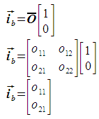
To calculate the pixel size in the i direction, the i unit vector is projected using the given transform. This gives the basis vector ib, the magnitude of which is the pixel size. The basis vector is expressed as follows:
The pixel size is then calculated as follows:
Pixel size in the j direction
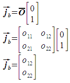
The pixel size in the j direction is computed in a manner similar to the pixel size in the i direction. The only difference is that the j unit vector is used in place of the i unit vector. This gives the basis vector jb, the magnitude of which is the pixel size. The basis vector is expressed as follows:
The pixel size is then calculated as follows:
The forward calculation
On the wiki page describing the reverse operation, a transform is developed which supports:
- scaling
- clockwise rotation around the origin
- shearing parallel to the x axis
- shearing parallel to the y axis
For the sake of consistency, we will use this same model and attempt to calculate the conceptually meaningful parameters from the transform coefficients. The above model produced the following equations:
- a11 = o11 = sx ( (1 + kx ky) cosθ + ky sinθ )
- a12 = o12 = sx ( kx cosθ + sinθ )
- a13 = tx
- a21 = o21 = sy ( -(1 + kx ky) sinθ + ky cosθ )
- a22 = o22 = sy ( - kx sinθ + cosθ )
- a23 = ty
where:
- sx : scale factor in x direction
- sy : scale factor in y direction
- tx : offset in x direction
- ty : offset in y direction
- θ : angle of rotation clockwise around origin
- kx : shearing parallel to x axis
- ky : shearing parallel to y axis
Solving for the meaningful parameters
The objective of this page is to find a way to determine values for sx, sy, tx, ty, θ, kx, and ky if all we know is a11,a12, ... a23. Clearly, tx and ty are trivial cases, because we can just use the values for a13 and a23 respectively. This leaves us with these four equations:
- a11 = o11 = sx ( (1 + kx ky) cosθ + ky sinθ )
- a12 = o12 = sx ( kx cosθ + sinθ )
- a21 = o21 = sy ( -(1 + kx ky) sinθ + ky cosθ )
- a22 = o22 = sy ( - kx sinθ + cosθ )
Unfortunately, these four equations contain five unknowns: sx, sy, θ, kx, and ky. This represents an ill-posed problem and forces us to simplify. Let's assume that there is no shearing. We are just going to declare upfront that kx=0 and ky=0. Remember that we did that because if we're wrong it will screw everything up. This makes the above into:
- a11 = o11 = sx cosθ
- a12 = o12 = sx sinθ
- a21 = o21 = - sy sinθ
- a22 = o22 = sy cosθ
Now we're on a roll. We can knock out sx and sy very easily:
- a112 + a122
- = sx2 cos2θ + sx2 sin2θ
- = sx2 (cos2θ + sin2θ)
- = sx2 (1)
- a212 + a222
- = (- sy)2 sin2θ + sy2 cos2θ
- = sy2 (sin2θ + cos2θ)
- = sy2 (1)
Rewriting as a "final result", this gives:
- sx2 = a112 + a122
- sy2 = a212 + a222
Checking against wikipedia
Checking this against the wikipedia page on the world file, which lists:
- "pixel width" = sx = sqrt(A2 + D2) = sqrt(a112 + a212)
- "pixel height" = sy = sqrt(B2 + E2) = sqrt(a122 + a222)
Clearly, this does not match the answer on our page. The three possibilities are: we made a mistake; they made a mistake; or no one made a mistake, but we're using different models... The world file page does not declare it's assumptions about what operations are performed, or which order they are performed in. The world file page, however, also defines it's parameter A (for us: a11) as "pixel size in x direction".
NOTE: If the order of the model operations changes, in particular if scaling and rotation are swapped, then these pages match wikipedia. However, the math on wikipedia is unsourced. Since it has become clear that order is vital, and it is by no means guaranteed that all software performs uses the same model, it is probably vital to go out and determine which software performs the calculations which way before we do anything else.
Attachments (13)
- geotransform.png (2.1 KB ) - added by 13 years ago.
- model.png (5.5 KB ) - added by 13 years ago.
- basisvector_i.png (2.0 KB ) - added by 13 years ago.
- basisvectormag_i.png (974 bytes ) - added by 13 years ago.
- basisvector_j.png (2.1 KB ) - added by 13 years ago.
- basisvectormag_j.png (1019 bytes ) - added by 13 years ago.
- calc_theta_i.png (6.2 KB ) - added by 13 years ago.
- thetamag_i.png (4.3 KB ) - added by 13 years ago.
- thetatest_i.png (4.6 KB ) - added by 13 years ago.
- calc_theta_ij.png (7.1 KB ) - added by 13 years ago.
- basisvector_ip.png (5.0 KB ) - added by 13 years ago.
- thetamag_ij.png (3.4 KB ) - added by 13 years ago.
- thetatest_ij.png (3.5 KB ) - added by 13 years ago.
Download all attachments as: .zip


